Mule Application Architecture
This page covers the structural features you can build into Mule applications.
About Mule
Mule ESB provides comprehensive application integration for small businesses and large enterprises alike. The Enterprise Service Bus (ESB) at Mule’s core facilitates intranet connections within an organization as well as secure external connections to Web-based APIs and other Cloud resources.
All Mule applications ---and their Cloud-based cousins known as iApps — are easy to build, because they leverage pre-packaged building blocks designed to “plug in” to the standardized interface provided by the Mule service bus.
The Studio interface provides a powerful “drag and drop” design canvas and application builder. A companion XML editing environment provides numerous conveniences for developers who prefer to edit code directly.
You can deploy Mule applications to the robust, yet lightweight Mule server that performs equally well in stand-alone and clustered topologies. The Management Console facilitates deployment to the Mule Repository and subsequent deployment to Mule clusters.
CloudHub (formerly known as Mule iON) provides a platform that speeds application deployment to the Cloud.
The powerful Anypoint DataMapper feature not only translates payloads from one data format to another; it can remap data fields as well as filter, enrich, and route payloads in sophisticated ways.
The Data Loader option relieves the pain and uncertainty of uploading large data sets to Web-based API services such as Salesforce and SAP.
A large and ever-expanding assortment of bundled and premium Connectors facilitates quick, easy Cloud-integration for the Mule applications you create.
About Mule Applications
At the simplest level, Mule applications accept one message at a time, processing received messages in the order they are received. Such processing can lead to a variety of results. Sometimes, the Mule application returns an altered or replacement message to the source of the original message. Additionally or instead, the application can send the message in its original or altered form to one or more third parties. In still other cases, Mule can decline to process the message if it has not met specific criteria.
Sophisticated Mule applications go far beyond this sort of linear message processing. Advanced mechanisms can process different messages in very different ways. Furthermore, you can construct applications that utilize:
-
various queue-and-thread arrangements to maximize throughput
-
transactionality or clustered nodes to maximize reliability
-
object stores to ensure data persistence
These represent only a fraction of the features you can implement through Mule applications.
About Mule Application Deployment
You can deploy Mule applications in the following three ways:
-
As a “zipped” archive file that contains your Mule application and all the code resources and configuration information necessary to make it run on an application server such as the Mule ESB standalone server.
-
To the Mule Repository, which you administer through the Mule Management Console. Use this option to deploy a Mule application to a clustered Mule topology.
-
To the CloudHub platform (formerly known as Mule iON).
About Mule Execution Units
Mule ESB supports several architectural approaches to building Mule applications. MuleSoft recommends Flows, the newest, most convenient, and most flexible method as the preferred architecture for most Mule applications. However, Configuration Patterns remain available, and may prove useful in certain specialized situations.
Flows
Flows provide the most powerful and flexible way to construct Mule applications, because you can arrange convenient, pre-packaged building blocks into a sequence of message-processing events tailored to your application needs.
Flows support synchronous and asynchronous child flows, one-way and request-response exchange-patterns, and other architectural options.
Flows can be particularly effective for the following use cases:
-
Simple integration tasks
-
Scheduled data processing
-
Integrating Cloud-based and on-premise applications
-
Event processing where multiple services need to be orchestrated
Mule provides a pair of interfaces for building Flows. You can choose between:
-
typing lines of code into an XML-based application configuration file
-
using Mule’s Studio graphical interface to arrange building block icons into visual sequences
Subsequently, you configure these sequenced building blocks using additional Studio graphical tools, or by editing XML code in the configuration file.
Configuration Patterns
Mule ESB provides pre-configured, easy-to-implement application patterns, which are optimized for common message-processing use cases. You set up this type of application through Studio’s XML editor.
The four pre-packaged Configuration Patterns are:
| If your use case isn’t covered by the group of Configuration Patterns bundled with Mule, you should use a Flow instead. |
About Flows
At the simplest level, Flows are sequences of message-processing events. As the following schematic illustrates, a message that enters a flow may be:
-
validated (filtered)
-
enriched (appended)
-
transformed into a new format
-
processed by custom-coded business logic
-
logged to a database
-
evaluated to determine what sort of response gets returned to party that submitted the original message

The units from which Flows are constructed are known generically as Building Blocks. In general, these correspond to icons on the Studio graphical canvas or XML elements within the Mule application configuration file.
The following screenshot illustrates a Flow laid out on the Studio graphical “canvas.”

The following code block represents the XML listing for that same Flow.
<?xml version="1.0" encoding="UTF-8"?>

<mule xmlns="http://www.mulesoft.org/schema/mule/core" xmlns:mulexml="http://www.mulesoft.org/schema/mule/xml" xmlns:http="http://www.mulesoft.org/schema/mule/http" xmlns:scripting="http://www.mulesoft.org/schema/mule/scripting" xmlns:doc="http://www.mulesoft.org/schema/mule/documentation" xmlns:spring="http://www.springframework.org/schema/beans" xmlns:core="http://www.mulesoft.org/schema/mule/core" xmlns:wmq="http://www.mulesoft.org/schema/mule/ee/wmq" xmlns:xsi="http://www.w3.org/2001/XMLSchema-instance" version="EE-3.2.2" xsi:schemaLocation="
http://www.mulesoft.org/schema/mule/xml http://www.mulesoft.org/schema/mule/xml/current/mule-xml.xsd
http://www.mulesoft.org/schema/mule/http http://www.mulesoft.org/schema/mule/http/current/mule-http.xsd
http://www.mulesoft.org/schema/mule/scripting http://www.mulesoft.org/schema/mule/scripting/current/mule-scripting.xsd
http://www.springframework.org/schema/beans http://www.springframework.org/schema/beans/spring-beans-current.xsd
http://www.mulesoft.org/schema/mule/core http://www.mulesoft.org/schema/mule/core/current/mule.xsd
http://www.mulesoft.org/schema/mule/ee/wmq http://www.mulesoft.org/schema/mule/ee/wmq/current/mule-wmq-ee.xsd ">
    <flow name="DemoFlow1" doc:name="DemoFlow1">
        <http:inbound-endpoint exchange-pattern="request-response" host="localhost" port="8081" doc:name="HTTP"/>
        <expression-transformer doc:name="Expression"/>
        <append-string-transformer message="" doc:name="Append String"/>
        <mulexml:xml-to-object-transformer doc:name="XML to Object"/>
        <component doc:name="Java"/>
        <logger level="INFO" doc:name="Logger"/>
        <scripting:component doc:name="Groovy">
            <scripting:script engine="Groovy"/>
        </scripting:component>
    </flow>
</mule>
Flow Building Blocks
Studio building blocks fall into several functional categories, some of which are processing blocks that comprise several building blocks themselves.
Not all building blocks can be occupy all positions within a flow. Often, the position of a building block in relation to the rest of the flow (or in relation to the building blocks in its immediate vicinity) greatly influences the behavior of the building block and how it must be configured.
The following sub-sections detail the various types of building blocks (and processing blocks) that can populate a Mule Flow.
Message Source (Optional)
The first building block in most Flows is a Message Source, which receives messages from one or more external sources, thus triggering a Flow instance. Each time it receives another message, the Message Source triggers another Flow instance.
Typically an Inbound Endpoint serves as a message source, although a streaming connector can perform this role as well.
Sometimes the Message Source immediately places the incoming message into a queue. This allows the Message Source to close the receiver thread it used to accept the message, and immediately open another thread to accept another incoming message. The message just placed into the queue waits until it reaches the head of the queue and can be processed through the rest of the Flow. Since the message is processed sequentially by two distinct threads (with an intervening wait inside the queue), start-to-finish transaction processing is not possible.

Sometimes, a Message Source can accept incoming messages from multiple transport channels. For instance, you can embed an HTTP endpoint and a Servlet endpoint into the same Message Source. Or you can create a Message Source to receive both IMAP and POP3 mail. Either embedded endpoint (i.e., transport channel) can trigger a Flow instance as soon as it receives an incoming message.
Under certain conditions, Flows do not need to be triggered by Message Sources. For instance, a Flow Reference Component can trigger a private, child Flow. Similarly, the Async Scope can trigger a child Flow that executes asynchronously, (i.e., in parallel with the parent Flow).
Message Processors
Typically, these are pre-packaged units of functionality that process messages in various ways. Except for Message Sources, all the building blocks in a Flow qualify as Message Processors. Message Processors offer the following advantages:
-
generally, they don’t have to be custom-coded
-
multiple Message Processors can be combined into various structures that provide the exact functionality you need for your application
You can assemble Message Processors into application (i.e., Flow) sequences in two distinct ways:
-
by arranging icons on the Studio canvas
-
by inserting XML code into the application configuration file
Message processors fall into a number of convenient categories, as the following table indicates:
| Category | Brief Description |
|---|---|
Endpoints |
They fall into two sub-categories (Inbound and Outbound), and provide a means for Mule applications to communicate with the outside world. |
Scopes |
They enhance, in a wide variety of ways, the functionality of other message processors or functional groups of message processors known as Processing Blocks. |
Components |
They allow you to enhance a Flow by attaching functionality such as logging, display output, and even child Flows. Alternatively, they facilitate Software as a Service (SaaS) integration by providing language-specific "shells" that make custom-coded business logic available to a Mule application. |
Transformers |
They prepare a message to be processed through a Mule flow by enhancing or altering the message header or message payload. |
Filters |
Singly and in combination, they determine whether a message can proceed through an application flow. |
Flow Controls |
They specify how messages get routed among the various Message Processors within a Flow. They can also process messages (i.e., aggregate, split, or resequence) before routing them to other message processors. |
Error Handlers |
They specify various procedures for handling exceptions under various circumstances. |
Connectors |
They facilitate integration of Mule applications with Web-based, 3rd-party APIs, such as Salesforce and Mongo DB. |
Miscellaneous |
This special category currently contains just one member: the Custom Business Event building block, which you place between other building blocks to record Key Performance Indicator (KPI) information, which you monitor through the Mule Console. |
After you have arranged the various building blocks in your flow into proper sequence, you may need to configure these message processors using one or both of the available options:
-
selecting from drop-down lists of available options or completing text fields in the Studio graphical interface
-
entering attribute values within the XML configuration code. (A nifty, predictive “auto-complete” feature eases this task greatly).
Message Processing Blocks
Mule provides several ways to combine multiple message processors into functional processing blocks.
For instance, the Composite Source scope allows you to embed into a single message source two or more inbound endpoints, each one listening to a different transport channel. Whenever one of these listeners receives an incoming message, it triggers a flow instance and starts the message through the message processing sequence.
Other building blocks known as Scopes provide multiple ways to combine message processors into convenient functional groups that can:
-
make your XML code much easier to read
-
implement parallel processing
-
create reusable sequences of building blocks
Endpoints
As previously mentioned, Endpoints implement transport channels that facilitate the insertion or extraction of data from Flows. Endpoints serve a diverse variety of roles, depending on how they are configured. For example, they can, as previously mentioned, serve as Inbound or Outbound conduits. They can implement one-way or request-response exchange patterns. And, in certain situations, you can embed other types of message processors, such as transformers or filters, into endpoints.
Inbound Endpoints
When placed at the start of a flow, either alone, or embedded with other endpoints in a Composite Source component, an endpoint is always referred to as an Inbound Endpoint, because it accepts messages from external sources and passes them to the rest of the flow, thereby triggering a new flow instance.
Not all flows require an Inbound Endpoint. For instance, a child Flow can be triggered by a Flow Reference which does not import any data into the child Flow.
Not all Endpoints can serve as inbound endpoints. For instance, the SMTP Endpoint can only serve as an Outbound Endpoint.
Outbound Endpoints
At the most basic level, Outbound Endpoints pass data out of a Flow. Often they occupy the final Message Processor position in a Flow, so when they pass data out of the flow, the Flow instance is considered complete.
However, an Outbound Endpoint can also appear in the middle of a Flow, passing data to a database as the rest of the Flow continues, for instance.
Not all Endpoints can serve as Outbound endpoints. For instance the POP3 and IMAP can only serve as Inbound Endpoints.
Outbound endpoints can also be configured for a request-response exchange pattern, as detailed in the following section.
Request-Response Endpoints
When Inbound Endpoints such as HTTP or VM are configured for a request-response pattern, they effectively become hybrid Inbound-Outbound endpoints. Even if other Outbound endpoints exist to conduct data out of the flow, the Inbound Endpoint configured for a request-response exchange pattern also conducts data out of the flow by returning a response to the original sender of the message.
When Outbound Endpoints are configured for request-response exchange patterns, they can exchange data with resources outside the flow or with a string of message processors entirely within the same Mule application, as depicted by the following schematic:

Not all endpoints can be configured for the request-response exchange pattern, and of those that can, request-response is the default exchange pattern for only some of them. To complicate matters further, certain cases exist (such as the JDBC Endpoint) where request-response is available, but only when the endpoint is configured as an outbound endpoint.
When none of the endpoints in a main flow is configured to the request-response exchange pattern, the flow follows a One-Way exchange pattern in which it receives incoming messages, but is not expected to provide any response to the original sender. However, the flow may send data to other parties such as a log file, a database, an email server, or a Web-based API.
Processing Strategies
A processing strategy determines how Mule executes the sequence of message processors in your application. For example, when the message source is configured for the request-response exchange pattern, Mule sets the processing strategy to Synchronous, which means that the entire flow gets executed on a single processing thread, thus ensuring that the entire sequence of message processors executes, and the client receives a response, as expected.
By contrast, when the flow is configured for a one-way, non-transactional exchange pattern (i.e., no response to the original message sender is required, and it isn’t necessary to verify that all steps in the flow have been completed), Mule sets the processing strategy to Queued Asynchronous, which has the potential to raise flow throughput. Under this processing strategy, the inbound endpoint places the incoming message into the queue as soon as it is received, then closes the receiver thread. When the message reaches the top of the queue, it resumes processing, but this time on a different thread. By implication, this sort of processing does not qualify as transactional end-to-end, because the transfer from one thread to the next means that the processing can not be rolled back if an exception is thrown.

For further details, see Flow Processing Strategies
Exception Strategies
An exception strategy determines how Mule responds if and when an error occurs during the course of message processing. In the simplest case, the error is simply logged to a file.
You can configure a custom exception strategy to respond in a variety of ways to a variety of conditions. For example, if an exception is thrown after a message has been transformed, you can set Mule to commit the message as it existed after being transformed, but immediately before the error occurred, so that the message cannot inadvertently be processed twice.
Studio provides four pre-packaged error handling strategies to handle exceptions thrown at various points during the message processing sequence. For details, see: Error Handling
Flow Architecture
Mule flows are extremely flexible, so you can combine building blocks in many ways, often to achieve the same result. For many use cases, however, certain message processors tend to fall into loosely ordered patterns. For example, suppose you wanted to create an application that receives product catalog requests from a Web page then sends a PDF of the catalog back to the client who submitted the request. In addition, you want this flow to record the client’s customer information to a database and log the transaction so that you can keep track of how many of each kind of catalog have been sent. Your flow might look something like this:

Note that you could embed the filter and the transformers inside the Inbound Endpoint, but placing them in the main Flow sequence makes the sequence of events easier to “read” on the Studio Message Flow canvas and in the XML-based application configuration file.


Child Flows
|
Key to Understanding the Schematics A solid line (below, left) indicates synchronous processing along a single thread, which is ideally suited to transactional processing. A dashed line (below, right) indicates simultaneous, parallel, asynchronous processing along multiple threads. |
Every flow-based Mule application is built around a main flow. Typically, processing for each message begins when the message source receives a message and concludes when the last message processor in the main flow completes its task. However, the main flow can also spawn various types of branch (i.e., child) flows that run synchronously or asynchronously, and can potentially provide the following advantages:
-
an asynchronous branch flow (which isn’t required to return data to the main flow) can perform potentially time-consuming tasks, such as writing data to an external database or emailing a message.
-
a child flow that handles operations considered much more (or much less) important than the tasks performed by the main flow can respond to errors differently from the main flow.
-
a child flow can make a complex application easier to “read”, either as an arrangement of icons on the Message Flow canvas or as code within the XML editor.
-
some child flows only need to be created once then can be reused multiple times throughout an application.
-
under certain circumstances, multiple child flows can promote high reliability by ensuring that crucial sequences of events get completed.
-
multiple child flows can be configured to execute on “the next available node” in a Mule cluster, thus promoting high availability and high throughput.
As the following sub-sections detail, child flows fall into two main categories: Synchronous and Asynchronous.
Synchronous
When a main flow triggers a synchronous child flow, it passes programmatic control to that child flow and suspends its own message processing activity until the child flow completes its sequence of message processing events and returns programmatic control to the main flow.

Since the main flow and the child flow hand off programmatic control to each other, and by implication, all processing occurs on the same thread, each event in the message processing sequence can be tracked, and transactional processing can be ensured.
|
Transactional processing handles a complex event (such as the processing of an individual message by a Mule application) as distinct, individual event that either succeeds entirely or fails entirely, and never returns an intermediate or indeterminate outcome. Even if only one of the many message processing events in a Mule application flow fails, the whole flow is considered to fail. The application can then “roll back” (i.e., undo) all the successully completed message processing steps so that, for instance, a customer invoice issued early in the flow is rescinded whenever one of the final steps in the flow, such as the physical mailing of the merchandise, fails to take place. Sometimes, in addition to rolling back all the steps in the original, failed processing instance, the application can recover the original message and reprocess it from the beginning. Since all traces of the previous, failed attempt have been erased, a single message ultimately produces a only single set of results. Typically, transactionality is difficult to implement for Mule flows that transfer processing control across threads, which occurs for most types of branch processing. However, certain measures (such as the use of VM endpoints at the beginning and end of each child flow that does not run on the main flow’s thread) can ensure that each of these child flows executes successfully as a unit, although this architecture does not ensure that each message processor within one of these child flows completes its task successfully. For details see: Two Queue Example. |
Subflows
Subflows, which always run synchronously, inherit both the processing strategy and exception strategy of the parent flow. This type of child flow, which is referenced through the Subflow component in the Studio palette, provides a number of potential advantages. First, a subflow can isolate logical processing blocks, making the underlying XML code much easier to read.
Subflows are ideally suited for code reuse, so a developer can write a particular block of code just once, then reference the same subflow repeatedly from within the same application.

Although a subflow operates synchronously, it can spawn an asynchronous child flow of its own, which executes in parallel, while the parent subflow and then the main flow continue to run.
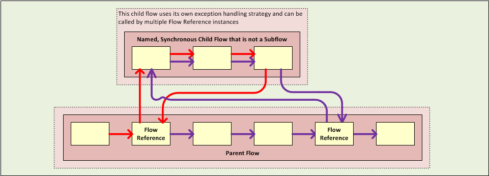
Synchronous Child Flows that are not Subflows
A special type of child flow operates synchronously, as a Subflow does, but unlike a Subflow, this type of synchronous child flow uses its own (rather than the parent flow’s) exception strategy. This can be useful when the message processing events inside the child flow are either much more or much less crucial than the rest of the events in the main flow. In either case, you can set the exception strategy used by the synchronous child flow to perform very differently from the exception strategy you configured for the main flow.
Asynchronous
Asynchronous Flows begin processing when triggered by the main flow (or a child flow that becomes its parent). Since this type of child flow does not need to return data to the parent flow, it can execute simultaneously with the main flow. In other words, when the main flow triggers the asynchronous flow, it neither passes programmatic control to the asynchronous flow, nor does it pause its own message processing until the asynchronous flow completes execution. In other words, the parent flow retains programmatic control throughout, without regard to the state of the asynchronous thread.
Calling Child Flows
The Flow Reference Component can call three distinct types of child flows.
The first type, known as a Subflows, is synchronous and always inherits both the processing strategy and exception strategy employed by the parent flow. While a Subflow is running, processing on the parent flow pauses, and it resumes only after the Subflow completes and hands control back to the parent flow. Also, because a subflow must be named, it can be referenced multiple times by Flow Reference Components scattered about the main flow.
The second type of child flow is called a Synchronous Child Flows that are not Subflows, which is named, and therefore can be reused just like a Subflow. Also just like a Subflow, a Synchronous Child Flow causes the parent flow to pause until it completes execution. However, unlike a Subflow, a Synchronous Child Flow does not inherit the exception strategy used by the parent flow. This allows special error handling measures to be applied to just the message processing events within the Synchronous Child Flow.
The third type of child flow you can call through the Flow Reference Component is called an Asynchronus Child Flow. Note that an asynchronous flow called in this manner must be named, and because it exists outside the parent flow, it can be called (i.e., reused) multiple times.
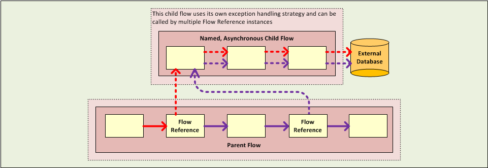
An Asynchronous Child Flow called by the Async Scope, rather than the Flow Reference Component, exists in-line (i.e., within the parent flow), and runs asynchronously on a separate thread while the main thread continues to run without pause.

The following table details the component to use for calling the various types of child flows:
| Type of Child Flow | Calling Component | In-line ? (i.e. not named and non-reusable) |
Execution | Exception Strategy |
|---|---|---|---|---|
Subflow |
Flow Reference |
No |
Synchronous |
Inherited |
Synchronous Child Flow |
Flow Reference |
No |
Synchronous |
Not Inherited |
Asynchronous Child Flow |
Flow Reference |
No |
Asynchronous |
Not Inherited |
Asynchronous Child Flow |
Async |
Yes |
Asynchronous |
Inherited |
Flow Configuration
Although flows consist of sequences of Studio building blocks, you cannot place any building block in any position within a flow. Additionally, the proximity or absence of certain building blocks within a sequence can determine whether a given building block can be placed at a certain point within a flow. Finally, depending where it resides in a flow, a given building block, especially an endpoint, can expose an significantly different set of attributes for configuration.
Fortunately, the graphical canvas in Mule Studio keeps track of all these contingencies, and it will not let you place a building block icon where it is not allowed.
Although it is impossible to cover all the possible sequences of building blocks that can produce workable flows, a typical flow might utilize the following sequence:
-
A Message Source consisting of one or more inbound endpoints triggers the flow each time it receives a message.
-
A Filter, which may be embedded in the message source or follow it in the main flow, may identify invalid messages and decline to pass them to the rest of the flow for processing.
-
A Transformer can convert the incoming message into a data format consumable by the other message processors in the flow. Like a filter, a transformer can be embedded within the message source or reside within the main flow.
-
A Message Enricher can append certain vital information to a message. For instance, if a message arrives with an address attached, the message enricher might use the postal code to look up the associated telephone area code, then append this information to the message header for marketing purposes.
-
After the message has been “prepared” for processing, it is generally sent to some pre-packed or custom business logic (usually called a Component) so that it can be processed in a manner appropriate for its particular content. Sometimes, external databases or APIs such as Salesforce are leveraged through building blocks known as connectors.
-
The final stages of a flow can vary considerably; some or all of the following can occur:
-
A response is returned to the original sender of the message.
-
The results of the business processing are logged to a database or sent to some other third party.
-
Throughout the flow, you can do the following:
-
configure queues (even more than one type on the same flow)
-
specify threading models
-
create child flows of various types
-
set exception strategies that apply to different parts of the application
Advanced Use Case
By judiciously combining the architectural options and product features available in Mule ESB, you can, with a minimum of development effort, design and create powerful, robust applications that fit your needs exactly.
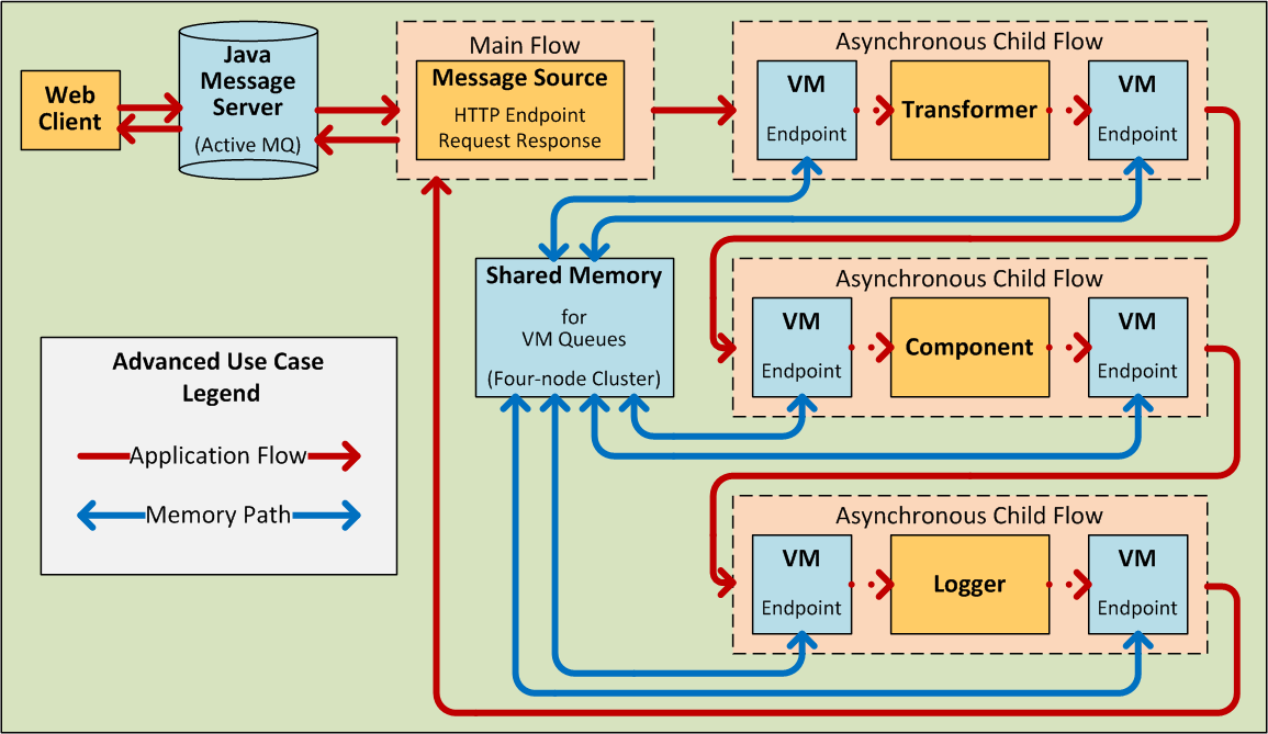
The application pictured below leverages child flows, two types of queues, clustering, and load balancing to create a Mule application that facilitates all of the following:
-
high throughput
-
high availability
-
high reliability (transactionality)
How It Works
Our application builds upon a request-response exchange pattern, in which Web clients submit messages (requests), then wait for responses from the application.
In this particular topology, A Java Message Server (JMS) sits between the clients and our application, receiving messages as they are submitted and managing them through Active MQ, a messaging queue that performs the following:
-
keeps track of every submission
-
forwards messages to the application in the order they were submitted
-
makes sure that our application provides a response to every message within a specified timeout period
-
forwards each response the the appropriate sender
Since the JMS sits outside the application, it is relatively slow compared to the rest of our application, which runs on multiple threads within our cluster of Mule nodes. Also, it does not have direct visibility into the success or failure of the individual message processing events within our application. Nevertheless, the JMS provides a form of “high-level transactionality” by ensuring that a response is received for each message.
Within our application, an HTTP endpoint set to the request-response exchange pattern serves as both the application’s message source (i.e., inbound endpoint) and its outbound endpoint, dispatching a response to each sender by way of the JMS.
The message processors within the main flow are segregated into three child flows, each of which begins and ends with a VM endpoint and also runs on a separate thread. These VM endpoints share memory through a VM queue. If any of the asynchronous child flows fails to execute successfully, the VM queue reports this, thus ensuring a type of flow-level transactionality known as high reliability.
Our application has been configured through the Mule Management Console to run on a four-node cluster. If any of the nodes go down, one of the others picks up the processing load, thus ensuring high availability.
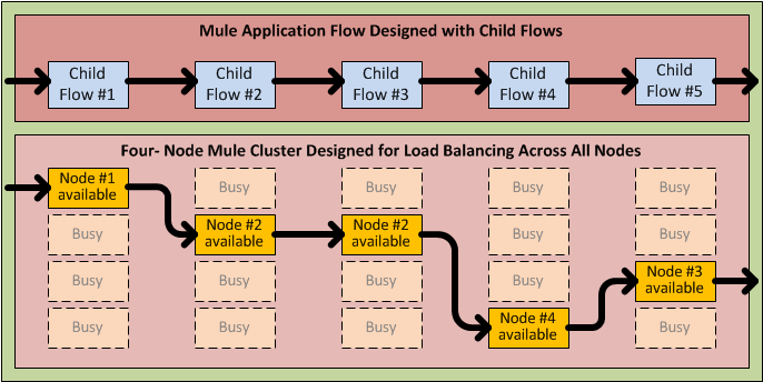
As the following diagram illustrates, even if none of the nodes goes down, the child flow “steps” can be processed on “the next available node.” This type of automatic load balancing promotes high throughput.
The above application stands as just one example of the many ways in which you can leverage Mule technology to speedily create and deploy powerful, custom-tailored Mule applications.
