Runtime Fabric Architecture
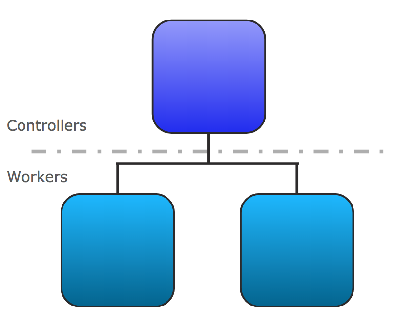
Anypoint Runtime Fabric is composed of a set of VMs that form a cluster. Each VM serves as either a controller node or a worker node.
-
Controller: a VM dedicated for operating Runtime Fabric, including orchestration services, a distributed database, load balancing, and services that enable you to manage the cluster from Anypoint Platform.
-
Worker: a VM dedicated for running Mule applications and API gateways. Mule applications and API proxies run on workers.
This separation of responsibilities enables scaling of the worker nodes based on the number of Mule applications. It also enables scaling the controller nodes based on the frequency of deployments, changes in application state, and amount of inbound traffic. To ensure resources are available to re-schedule and re-deploy applications in the event of a hardware failure, MuleSoft recommends over-provisioning the number of worker nodes.
By default, the services operating Runtime Fabric are deployed across the controller nodes to avoid a single point of failure in the system.
Anypoint Runtime Fabric uses a set of technologies, including Docker and Kubernetes, which are tuned to operate well with Mule runtimes. Knowledge of these technologies is not required to deploy or manage Mules on Runtime Fabric. Managing Runtime Fabric requires the operational and infrastructure-level experience needed to support any system at scale. We recommend following best practices and running fire drill scenarios in controlled environments to help prepare for unexpected failures.
| Deployments of applications and gateways not powered by Mule on Anypoint Runtime Fabric is not supported. |
Development and Production Configurations
Anypoint Runtime Fabric supports development and production configurations. These supported configurations specify the minimum nodes and resources required.
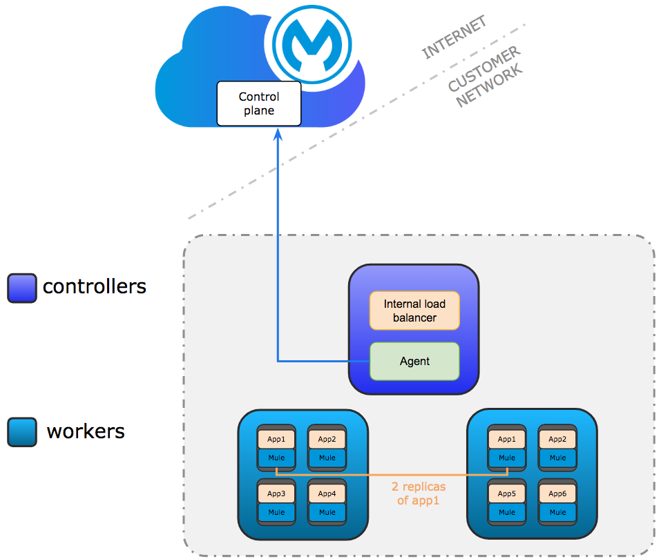
Development Configuration
The development configuration is intended for testing only. It requires at least one controller and two worker nodes. The controller node runs the internal load balancer and agents used to connect to Anypoint Platform. Communication between the agent and Anypoint Platform is always outbound. Multiple replicas of application can run across workers.
Production Configuration
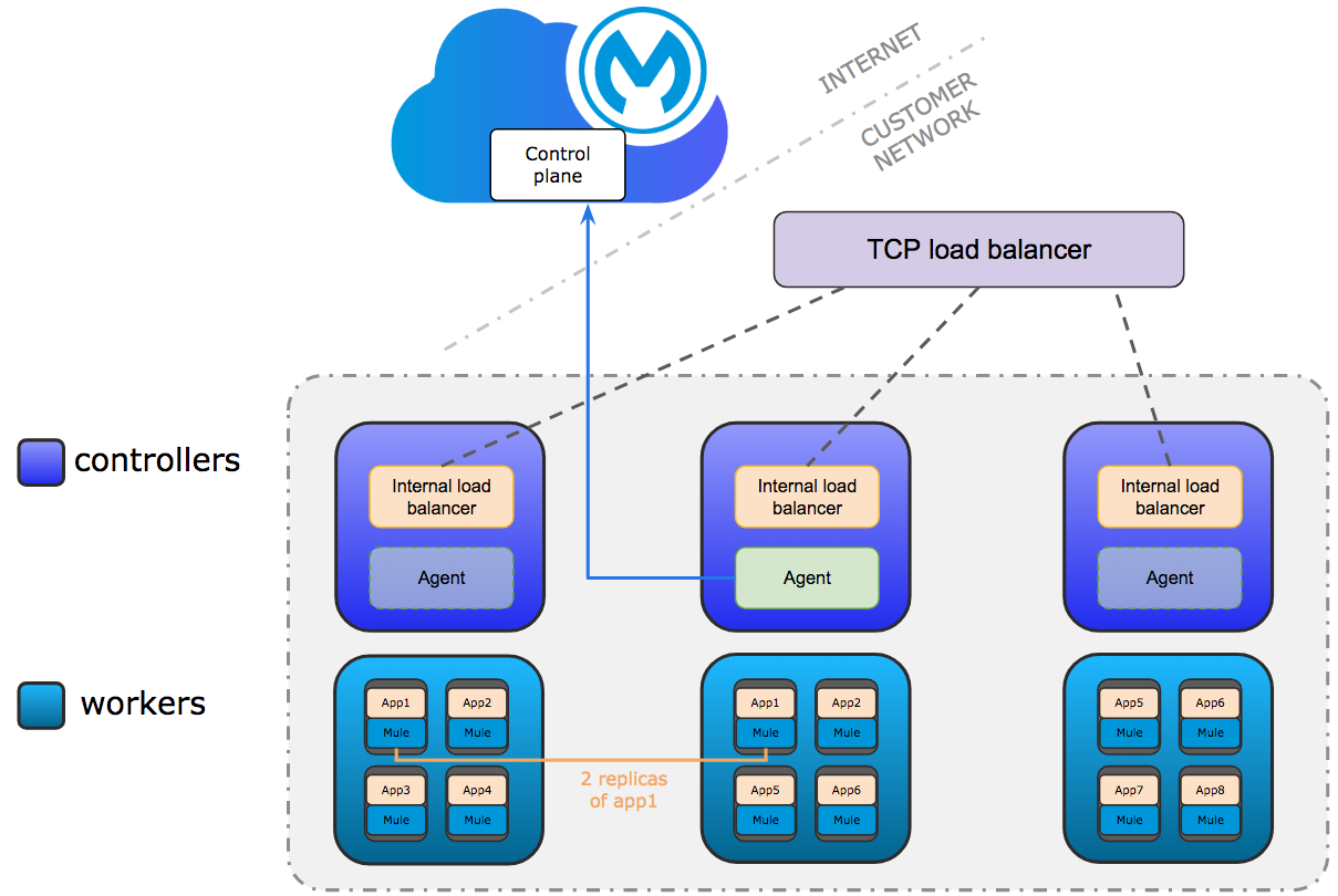
Only controllers run the internal load balancer and agents used to connect to Anypoint Platform.
Agents can run on any controller. Agent communication is always outbound.
The minimum requirements are 3 controller and 3 worker nodes. 3 controllers enable a fault-tolerance of losing 1 controller. To improve fault-tolerance to lose 2 controllers, a total of 5 controllers should be configured.
Mule applications run on workers. Multiple replicas of applications can run across workers.
Network Architecture
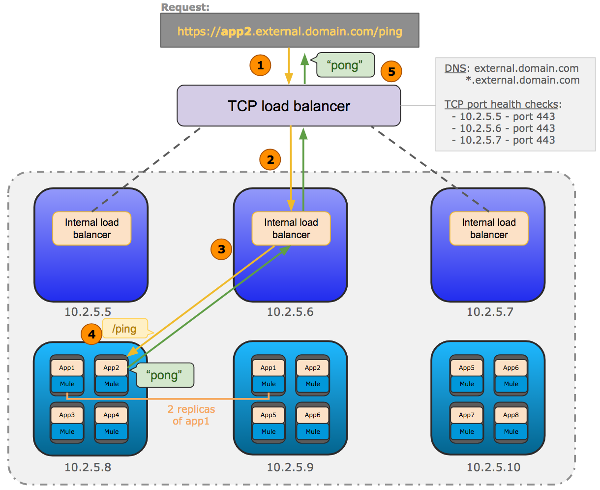
The following diagram shows the general network architecture of Runtime Fabric.
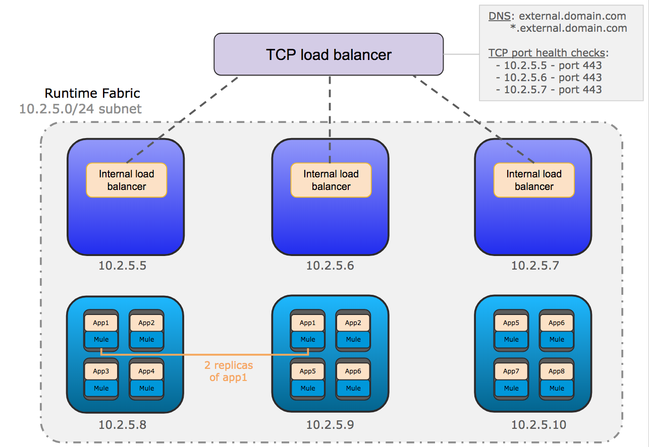
This diagram shows the TCP load balancer used to load balance requests across the internal load balancers running on the controllers. It also shows the internal load balancer that distributes requests to each replica of Mule applications running on the workers.
For internal load balancers:
-
Shared Mode is the default setting if no dedicated internal load balancer node is added in Runtime Fabric. In this mode, the internal load balancer runs on all controller nodes with the specified amount of CPU and memory.
-
Dedicated Mode is a setting that is available if one or more dedicated internal load balancer nodes are available in Runtime Fabric. All available resources in these nodes are used for running the internal load balancer, so the options to specify the amount of CPU cores and memory are not available.
-
The incoming HTTP request is forwarded to the external TCP load balancer.
-
The TCP load balancer forwards the request to an available internal load balancer on Runtime Fabric.
-
The internal load balancer decrypts the request and directs it to an available replica of the Mule application (app2) in the diagram above.
-
The application sends a response which is routed back to the requester.